A.) Combination of cells when emf of cells are same:
There are three types of combinations of cells in the circuit
1.) Series Combination of Cells
2.) Parallel Combination of Cells
3.) Mixed Combination of Cells
1.) Series Combination of Cells: Let us consider that the $n$ - cells having emf (electromotive force) $E$ and internal resistance $r$ are connected in series with external resistance $R$. Then from the figure given below
The total emf of the $n$ - cell = $nE$
The total internal resistance of the $n$ - cell = $nr$
The total resistance of the circuit = $nr+R$
The total current in the circuit
$i=\frac{Total \: emf \: of \: the \: n - series \: cell}{Total \: resistance \: of \: the \: circuit}$
$i=\frac{nE}{nr+R}$
2.) Parallel Combination of Cells: Let us consider that the $n$ - cells having emf (electromotive force) $E$ and internal resistance $r$ are connected in parallel with external resistance $R$. Then from the figure given below
The total emf of the $n$ - cell = $E$
The total internal resistance of the $n$ - cell
$\frac{1}{r_{eq}} = \frac{1}{r}+ \frac{1}{r}+.........n \: times$
$\frac{1}{r_{eq}}=\frac{n}{r}$
$r_{eq}=\frac{r}{n}$
The total resistance of the circuit = $\frac{r}{n}+R$
The total current in the circuit
$i=\frac{Total \: emf \: of \: the \: n - parallel \: cell}{Total \: resistance \: of \: the \: circuit}$
$i=\frac{E}{\frac{r}{n}+R}$
$i=\frac{E}{\frac{r+nR}{n}}$
$i=\frac{nE}{r+nR}$
3.) Mixed Combination of Cells: Let us consider that the $n$ - cells having emf (electromotive force) $E$ and internal resistance $r$ are connected in series in each row of $m$ parallel rows with external resistance $R$. Then from the figure given below
The total emf of the $n$ - cell in each row of $m$ parallel rows of the cells = $nE$
The internal resistance of the $n$ - cell in each row = $nr$
The total internal resistance of the $n$ - cell in each of $m$ parallel rows of the cells = $nr$
$\frac{1}{r_{eq}} = \frac{1}{nr}+ \frac{1}{nr}+.........m \: times$
$\frac{1}{r_{eq}}=\frac{m}{nr}$
$r_{eq}=\frac{nr}{m}$
The total resistance of the circuit = $\frac{nr}{m}+R$
The total current in the circuit
$i=\frac{Total \: emf \: of \: the \: cell}{Total \: resistance \: of \: the \: circuit}$
$i=\frac{nE}{\frac{nr}{m}+R}$
$i=\frac{nE}{\frac{nr+mR}{m}}$
$i=\frac{mnE}{nr+mR}$
It is clear from the above equation that for the value of $i$ to be maximum, the value of $(nr+mR)$ should be minimum. Now,
$nr+mR= \left[ \sqrt{nr}-\sqrt{mr} \right]^{2}+2 \sqrt{mnRr}$
Therefore, for $(nr+mR)$ to be minimum, the quantity $\left[ \sqrt{nr}-\sqrt{mr} \right]^{2}$ should be minimum. So
$\left[ \sqrt{nr}-\sqrt{mr} \right]^{2} = 0$
$ \sqrt{nr}-\sqrt{mr} = 0$
$ \sqrt{nr} = \sqrt{mr} $
$nr=mR$
$R=\frac{nr}{m}$
Here, $\frac{nr}{m}$ is the total resistance of the cells.
Thus, When the total internal resistance of the cells are equal to the external resistance then the total current in the external circuit will be maximum in the mixed combination of cells.
Showing posts with label Current Electricity. Show all posts
Showing posts with label Current Electricity. Show all posts
Relation between electromotive force (E), internal resistance (r) and potential difference (V) in a circuit
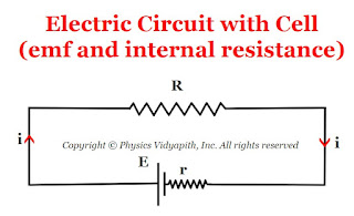
Relation between electromotive force $(E)$, internal resistance $(r)$ and potential difference $(V)$:
Let us consider:
The cell having electro-motive force = $E$
The cell having internal resistance = $r$
The external resistance of the circuit = $R$
The potential difference between the external resistance of the circuit = $V$
The current in circuit = $i$
So, The emf of the cell from the given circuit in the figure above
$E=iR+ir$
$E = V+ir$
$V=E-ir$
Difference between Potentiometer and Voltmeter
There are the following differences between a potentiometer and a voltmeter given below:
Potentiometer:
1.) It is based on null method.
2.) It gives an accurate value of emf.
3.) While measuring emf, it does not draw any current from the cell.
4.) Resistance of potentiometer wire becomes infinite while measuring emf.
5.) It can be used for various experimental purposes.
6.) It can not be taken conveniently from one place to another place.
Voltmeter:
1.) It is based on the deflection method.
2.) It does not give an accurate value of emf.
3.) While measuring emf, it draws some current from the cell. Hence it reads slightly less than the actual emf.
4.) The resistance of the voltmeter is high enough but not infinite.
5.) It can be used to measure potential differences only.
6.) It can be conveniently taken from one place to another place.
Principle construction and working of potentiometer
Potentiometer- An ideal voltmeter that does not change the original potential difference, needs to have infinite resistance. But a voltmeter cannot be designed to have infinite resistance. The potentiometer is one such instrument that does not draw any current from the circuit and still measures the potential difference. so it behaves as an ideal voltmeter.
"A potentiometer is an instrument. This is used to measure the potential difference between two points of an electric circuit and emf of a cell."
Principle-
The principle of the potentiometer depends upon the potential gradient along the wire i.e. "When a constant current flows in a wire then the potential drops per unit length of the wire".
Construction- A potentiometer consists of a long wire $AB$ of uniform cross-section, usually, this wire is $4 m$ to $10 m$ long and it is made of the material having high resistivity and low-temperature coefficient such as manganin or constant. Usually, $1m$ long-separate pieces of wire are fixed on a wooden board. These pieces of wires are parallel to each other and joined in series by thick copper strips. A meter scale is used to measure the position of the jockey on the wire and it is fixed parallel to the wire ( As shown in the figure). The ends $A$ and $B$ are connected to a strong battery, a plug key $(K)$, and a rheostat $(Rh)$. The circuit is called a driving or auxiliary circuit that sends a constant current $i$ through the wire $AB$. Thus the potential gradually drops from $A$ to $B$. This potential drop is measured with the help of a jockey and voltmeter. A jockey is used to make point contact on the wire and it slides on the wire along the length of the wire.
Working-
When a constant current flow through a wire of uniform cross-section area and composition, the potential drop across any length of the wire is directly proportional to that length.
If the voltmeter is connected between the end $A$ and Jockey $j$, it reads the potential difference $V$ across the length of the wire $AJ$. So according to ohm's law-
$V=iR$
$V=i \rho \frac{l}{A} \qquad(1)$
for a wire $\rho,i,A$ are constants. So
$\frac{i \: l}{A}=K (Constant)$
Hence equation $(1)$ can be written as
$V=Kl$
$V \propto l$
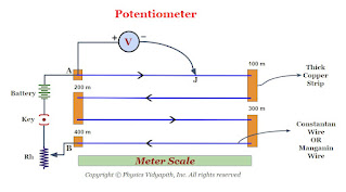 |
| Diagram of Potentiometer |
Metre Bridge OR Slide Wire Bridge
What is Metre Bridge?
$\frac{P}{Q}=\frac{R}{S}$
Construction: It consists of usually one-meter long manganin wire of uniform cross-section, stretched along a meter scale fixed over a wooden board and with its two ends soldered to two L-shaped thick copper strips $A$ and $C$. Between these two copper strips, another copper strip is fixed so as to provide two gaps $mn$ and $m_{1}n_{1}$. A resistance box (R.B.) is connected in the gap $mn$ and the unknown resistance $S$ is connected in the gap $m_{1}n_{1}$. A cell of emf $E$, Key $(K)$, and rheostat are connected across $AC$. A movable jockey and a galvanometer are connected across the $BD$, as shown in the figure.
Working:
In a Metre bridge, First take out the suitable resistance $R$ from the resistance box after that move the jockey along the wire $AC$ till there is not any deflection in the galvanometer. This is the condition of a balanced Wheatstone's bridge. If $P$ and $Q$ are the resistance of the part $AB$ and $BC$ of the wire, then for the balanced condition of the bridge, we have,
$\frac{P}{Q}=\frac{R}{S} \qquad(1)$
Let us consider:
The total length of the wire $AC=100 \: cm$
Length of the part $AB$ of wire = $l \: cm$
Length of the part $BC$ of wire = $(100-l) \: cm$
Resistance per unit length of the wire = $\sigma$
Resistance of wire of uniform cross-section = $\infty$
$\frac{P}{Q}=\frac{Resistance \: of \: AB}{Resistance \: of \: BC}$
$\frac{P}{Q}=\frac{\sigma l }{\sigma \left( 100-l \right) }$
$\frac{P}{Q}=\frac{ l }{ \left( 100-l \right) } \qquad (2)$
Now substitute the value of equation $(2)$ in equation $(1)$ then we get
$\frac{R}{S}=\frac{ l }{ \left( 100-l \right) } $
$S=\frac{R(100-l)}{l}$
Where
$S$ → Unknown Resistance
$R$ →Standard Resistance
It is the simplest practical application of the Wheatstone's bridge that is used to measure an unknown resistance.
Principle: Its working is based on the principle of Wheatstone's Bridge.
When the Wheatstone's bridge is balanced
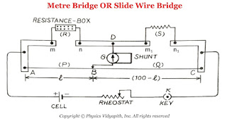 |
| Metre Bridge Or Slide Wire Bridge |
Length of the part $AB$ of wire = $l \: cm$
Length of the part $BC$ of wire = $(100-l) \: cm$
Resistance per unit length of the wire = $\sigma$
Resistance of wire of uniform cross-section = $\infty$
$R$ →Standard Resistance
Wheatstone's Bridge
It is an arrangement of four resistance used to determine one of this resistance quickly and accurately in terms of the remaining three resistance.
Objective:
To find the unknown resistance with the help of the remaining three
resistance.
Principle of Wheatstone Bridge: The principle of Wheatstone bridge is based on the
principle of Kirchhoff's Law.
Construction:
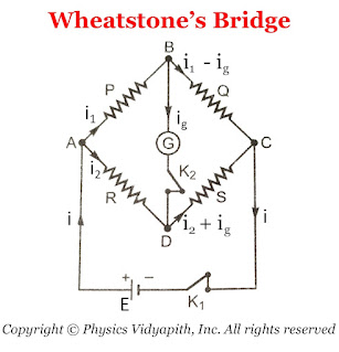
A Wheatstone bridge consists of four resistance $P$,$Q$,$R$, and $S$. This resistance is connected to form quadrilateral $ABCD$. A battery of EMF $E$
is connected between point $A$ and $C$ and a sensitive galvanometer is connected
between point $B$ and $D$ Which is shown in the figure below.
Working:
To find the unknown resistance $S$, The resistance $R$ is to be adjusted
like there is no deflection in the galvanometer. which means that there is not
any flow of current in the arm $BD$. This condition is called "Balanced
Wheatstone bridge" i.e
$\frac{P}{Q}=\frac{R}{S}$
Derivation of Balanced Condition of Wheatstone's Bridge: In accordance with
Kirchhoff's first law, the currents through various branches are shown in the figure
above.
For Close Loop $ABDA$
$0=P \: I_{1} - R \: I_{2} +G \: I_{g} \qquad(1)$
For Close Loop $CBDC$
$0=Q \left( I_{1} - I_{g} \right) -S \left( I_{2} + I_{g} \right) - G\: I_{g}
\qquad(2)$
For Balanced Wheatstone Bridge: $I_{g}=0$
SO from equation $(1)$ and equation $(2)$
$0=P \: I_{1} - R \: I_{2} $
$P \: I_{1} = R \: I_{2} \qquad(3)$
$0=Q I_{1} -S I_{2}$
$Q I_{1} = S I_{2} \qquad(4)$
Now divide the equation $(4)$ and equation $(3)$, then we get
$\frac{P}{Q}=\frac{R}{S}$
 |
| Diagram of Wheatstone's Bridge |
Kirchhoff's laws for an electric circuits
Kirchhoff's laws: Kirchhoff had given two laws for electric circuits i.e.
- Kirchhoff's Current Law or Junction Law
- Kirchhoff's Voltage Law or Loop Law
- Kirchhoff's Current Law or Junction Law: Kirchhoff's current law state that
The algebraic sum of all the currents at the junction in any electric circuit is always zero.$\sum_{1}^{n}{i_{n}}=0$Sign Connection: While applying the KCL, the current moving toward the junction is taken as positive while the current moving away from the junction is taken as negative.
So from figure,the current $i_{1}$,$i_{2}$,$i_{5}$ is going toward the junction and the current $i_{3}$,$i_{4}$, So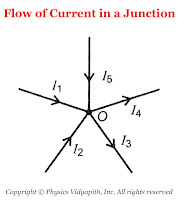
The flow of Current in a junction $\sum{i}= i_{1}+i_{2}+(-i_{3})+(-i_{4})+i_{5}$According to KCL $\sum{i}= 0$, Now the above equation can be written as$i_{1}+i_{2}+(-i_{3})+(-i_{4})+i_{5}=0 \qquad$$i_{1}+i_{2}+i_{5}=i_{3}+i_{4}$Thus, the sum of current going towards the junction is equal to the sum of current going away from the junction.In other words, at any junction, neither the charge accumulates nor the charge is removed. So this law represents conservation of charge. -
Kirchhoff's Voltage Law or Loop Law: Kirchhoff's voltage law state that:
The algebraic sum of all the voltage or emf in any closed loop of an electric circuit is always zero.$\sum_{1}^{n}{E_{n}}=0$This means that the algebraic sum of all the emf applied in any closed loop is always equal to the algebraic sum of the product of current and resistance in the closed loop.$\sum{E}=\sum {i.R}$Sign Connection: While applying this law, a product of current and resistance is taken as positive when we traverse in the direction of the conventional current and the emf is taken positively when we traverse from negative to the positive electrode through the electrolyte.
So from the figure: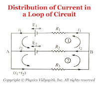
Distribution of Current in a Loop of Circuit For Mesh $(1)$$E_{1}-E_{2}=i_{1}R_{1}-i_{2}R_{2} \qquad(1)$For Mesh $(2)$$E_{2}=i_{2}R_{2}+\left( i_{1}+i_{2} \right)R_{3} \qquad(2)$
Mechanism of Flow of Charge in Metals: Free Electron Gas Theory
Theory of Free Electron Gas Model →
According to the electron gas theory
1. The free electrons are continuous in motion inside the metal. The motion of free electrons are random inside the metal.
2. When the free electrons are collisied to each other then the direction of electrons are changed.
3. Mean free Path: The length covered by free electrons, between the two successive collisions is called the "Mean Free Path".
4. Relaxation Time: The time taken between the two successive collisions of free electrons is called the Relaxation time. It is represented by $\tau$.
5. Drift velocity: When a potential is applied across the metal then these electrons do not move own velocity but it move with an average velocity in the opposite direction of the electric field. This average velocity is called the "Drift Velocity". The drift velocity of electrons depends upon the applied potential.
6. Mobility of Electrons: When a potential $V$ is applied across the metal then electrostatic force $F$ acts on the electrons i.e
$F=qE $
$F=NeE \qquad(1)$
Where
$N$ →The number of free electrons inside the metal
$E$ → The electric field due to the applied potential
When this electrostatic force is applied to the electrons then these electrons are accelerated with accelerated $a$ i.e
$F=ma \qquad(2)$
From equation $(1)$ and equation $(2)$ we can write
$ma=N\:e\:E$
$a=\frac{N}{m}eE$
$\frac{v_{d}}{\tau}=\frac{N}{m}eE \qquad \left( \because a=\frac{v_{d}}{\tau} \right)$
$v_{d}=\frac{Ne\tau}{m} E$
$v_{d}=\mu E$
Where $\mu=\frac{Ne\tau}{m}$. It is known as the mobility of electrons.
$N$ →The number of free electrons inside the metal
$E$ → The electric field due to the applied potential
Derivation of Ohm's Law
Derivation→
Let us consider,
The length of the conductor = $l$
The cross-section area of the conductor = $A$
The potential difference across the conductor = $V$
The drift velocity of an electron in conductor = $v_{d}$
Now from the equation of the mobility of electron i.e.
$v_{d}= \mu E$
$v_{d}= \left( \frac{e\tau}{m} \right) E \qquad \left(\because \tau = \frac{e\tau}{m} \right)$
$v_{d}= \left( \frac{e\tau}{m} \right) \frac{V}{l}\qquad (1) \qquad \left(\because E = \frac{V}{l} \right)$
Now from the equation of drift velocity and electric current
$i=neAv_{d}$
Now substitute the value of $v_{d}$ from equation $(1)$ to above equation
$i=neA\left( \frac{e\tau}{m} \right) \frac{V}{l}$
$i=\left( \frac{ne^{2}A\tau}{ml} \right)V$
$\frac{V}{i}=\left( \frac{ml}{ne^{2}A\tau} \right)$
$\frac{V}{i}=R$
Where $R = \frac{ml}{ne^{2}A\tau} $ is known as electrical resistance of the conductor.
Thus
$V=iR$
This is Ohm's Law.
The cross-section area of the conductor = $A$
The potential difference across the conductor = $V$
The drift velocity of an electron in conductor = $v_{d}$
Relation between electric current and drift velocity
Derivation→
Let us consider
The length of the conductor = $l$
The cross-section area of the conductor = $A$
The total number of free electrons inside the conductor = $N$
The current flow in the conductor = $i$
The Relaxation time between the two successive collisions =$\tau$
According to the law of current density
$J=\frac{i} {A} $
$J=\frac{q} {A \tau} \qquad \left( \because i=\frac{q}{\tau} \right)$
$J=\frac{N \: e }{A \tau} \qquad \left( \because q=Ne \right)$
Now multiply by length of conductor $l$ in above equation. Therefore we get
$J=\frac{N \: e \: l}{A \tau\: l} $
$J=\frac{N \: e \: l}{V \tau\: }\qquad \left(\because V=A.l \right)$
Where $V$ is volume of the conductor.
$J=\frac{n \: e \: l}{ \tau }\qquad \left( \because n=\frac{N}{V} \right)$
Where $n$ is total number of electrons per unit .
$J=n \: e \: v_{d}\qquad \left( \because v_{d}=\frac{l}{\tau}\right)$
Where $v_{d}$ are known as drift velocity of charged particles.
Now substitute the value of current density $J$ from equation $(1)$ to above equation then above equation can be written as
$i=neAv_{d}$
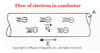 |
| The flow of Electron in Conductor |
Popular Posts
-
Let $S$ be a point monochromatic source of light of wavelength $\lambda$ placed at the focus of collimating lens $L_{1}$. The light beam is ...
-
Angle of Acceptance → If incident angle of light on the core for which the incident angle on the core-cladding interface equals the crit...
Categories
Alternating Current Circuits
(10)
Atomic and Molecular Physics
(4)
Biomedical
(1)
Capacitors
(6)
Classical Mechanics
(12)
Current carrying loop in magnetic field
(4)
Current Electricity
(10)
Dielectric Materials
(1)
Electromagnetic Induction
(3)
Electromagnetic Wave Theory
(23)
Electrostatic
(20)
Energy Science and Engineering
(2)
Error and Measurement
(2)
Gravitation
(11)
Heat and Thermodynamics
(3)
Kinematics Theory Of Gases
(2)
Laser System & Application
(12)
Magnetic Effect of Current
(9)
Magnetic Substances
(2)
Mechanical Properties of Fluids
(5)
Nanoscience & Nanotechnology
(5)
Nuclear Physics
(7)
Numerical Problems and Solutions
(2)
Optical Fibre
(5)
Optics
(25)
Photoelectric Effect
(3)
Quantum Mechanics
(37)
Relativity
(9)
Semiconductors
(2)
Superconductors
(1)
Topic wise MCQ
(9)
Units and Dimensions
(1)
Waves
(5)


.jpg)

