Alternating Current Circuit containing Capacitance only (C-Circuit)
Alternating Current Circuit Containing Capacitance Only (C-Circuit): Let us consider, A circuit containing a capacitor of capacitance $C$ only which is connected with an alternating EMF i.e electromotive force source i.e.
Let us consider, A circuit containing a coil of inductance $L$ only which is connected with an alternating EMF i.e electromotive force source i.e.
$E=E_{\circ}sin\omega t\qquad(1)$
When alternating emf is applied across the capacitor plates then the charge on capacitor plates varies continuously and correspondingly current flows in the connecting leads. Let the charge on the capacitor plates is $q$ and the current in the circuit at any instant is $i$. Since there is no resistance in the circuit then the instantaneous potential difference is $\frac{q}{C}$ across the capacitor plates must be equal to the applied emf i.e.
$\frac{q}{C} = E_{\circ} sin \omega t$
$q = CE_{\circ} sin \omega t \qquad(2)$
The instantaneous current $i$ in the circuit is, therefore
$i=\frac{dq}{dt} \qquad(3)$
Now substitute the value of $q$ from equation $(2)$ to equation $(3)$
$i=\frac{d}{dt} CE_{\circ} sin \omega t $
$i=CE_{\circ} \omega cos\omega t$
$i=\omega CE_{\circ} cos\omega t$
$i=\frac{E_{\circ}}{\frac{1}{\omega C}} cos\omega t$
$i=\frac{E_{\circ}}{X_{C}} cos\omega t$
Where $X_{C}= \frac{1}{\omega C}$ is known as capacitive reactance.
$i=i_{\circ} cos\omega t \qquad(4)$
Where the $i_{\circ}=\frac{E_{\circ}}{X_{C}}$ is the maximum current in the circuit. Now apply Ohm's law in this equation and we find that the term $X_{C}=\frac{1}{\omega C}$ has the dimension of resistance. It represents the 'effective opposition' of the capacitor to the flow of alternating current. It is known as the 'reactance of the capacitor' or 'capacitive reactance' and is denoted by $X_{C}$. The capacitive reactance is infinite for DC for which $f=0$.
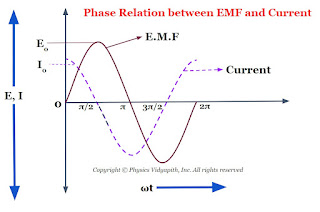
$i=i_{\circ} sin \left( \omega t + \frac{\pi}{2} \right) \qquad(4)$
Now compare equation $(1)$ and equation $(4)$ which shows that an alternating circuit containing a capacitor only, the current leads the emf by a phase angle of $\frac{\pi}{2}$ or $90^\circ$ (or the emf lags behind the current by a phase angle of $\frac{\pi}{2}$). The phase diagram between EMF and the current of a capacitor is shown below-
The phasor diagram between the EMF and current of a capacitor is also shown in the given figure below-


