Alternating Current Circuit containing Inductance only (L-Circuit)
Alternating Current Circuit Containing Inductance only (L-Circuit): Let us consider, An alternating current circuit containing a coil of inductance $L$ only. This inductor is connected with an alternating EMF i.e electromotive force source i.e.
$E=E_{\circ}sin\omega t\qquad(1)$
The current $i$ in coil varies continuously then an opposite emf is induced in the coil whose magnitude is $L\frac{di}{dt}$ So the net instantaneous of the circuit:
$E_{\circ}sin\omega t -L\frac{di}{dt}=0$
$E_{\circ}sin\omega t =L\frac{di}{dt}$
$di=\frac{E_{\circ}}{L}sin\omega dt$
Now integrate the above equation then the above equation can be written as
$\int di=\int \frac{E_{\circ}}{L}sin\omega dt$
$\int di= \frac{E_{\circ}}{L} \int sin\omega dt$
$i= \frac{E_{\circ}}{L} \frac{-cos\omega t}{\omega}$
$i= -\frac{E_{\circ}}{\omega L} cos\omega t$
$i= -\frac{E_{\circ}}{X_{L}} cos\omega t$
Where $X_{L}= \omega L$ is known as inductive reactance.
$i= -i_{\circ} cos\omega t$
Where $i_{\circ}=\frac{E_{\circ}}{X_{L}}$ is known as the maximum value of current in the circuit. Now compare this equation to Ohm's law then we find that the term $X_{L}=\omega L$ has the dimensions of resistance. It defines the 'effective opposition' of the coil to the flow of alternating current. it is known as the 'reactance of the coil' or 'inductive reactance' and it is denoted by $X_{L}$. The inductive reactance $X_{L}$ is zero for DC at which frequency is zero.
$i= -i_{\circ} sin \left(\frac{\pi}{2}- \omega t \right)$
$i= i_{\circ} sin \left(\omega t - \frac{\pi}{2} \right) \qquad(2)$
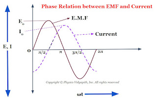
Now compare equation $(1)$ and equation $(2)$ which shows that an alternating circuit containing an inductor only, the current lags behind the emf by a phase angle of $\frac{\pi}{2}$ or $90^\circ$ (or the emf leads the current by a phase angle of $\frac{\pi}{2}$). The phase diagram between EMF and the current of an inductor is shown below-
The phasor diagram between the EMF and current of an inductor is also shown in the given figure below-


