Kirchhoff's laws for an electric circuits
Kirchhoff's laws: Kirchhoff had given two laws for electric circuits i.e.
- Kirchhoff's Current Law or Junction Law
- Kirchhoff's Voltage Law or Loop Law
- Kirchhoff's Current Law or Junction Law: Kirchhoff's current law state that
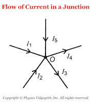
The algebraic sum of all the currents at the junction in any electric circuit is always zero.$\sum_{1}^{n}{i_{n}}=0$Sign Connection: While applying the KCL, the current moving toward the junction is taken as positive while the current moving away from the junction is taken as negative.
So from figure,the current $i_{1}$,$i_{2}$,$i_{5}$ is going toward the junction and the current $i_{3}$,$i_{4}$, So
The flow of Current in a junction $\sum{i}= i_{1}+i_{2}+(-i_{3})+(-i_{4})+i_{5}$According to KCL $\sum{i}= 0$, Now the above equation can be written as$i_{1}+i_{2}+(-i_{3})+(-i_{4})+i_{5}=0 \qquad$$i_{1}+i_{2}+i_{5}=i_{3}+i_{4}$Thus, the sum of current going towards the junction is equal to the sum of current going away from the junction.In other words, at any junction, neither the charge accumulates nor the charge is removed. So this law represents conservation of charge. -
Kirchhoff's Voltage Law or Loop Law: Kirchhoff's voltage law state that:
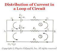
The algebraic sum of all the voltage or emf in any closed loop of an electric circuit is always zero.$\sum_{1}^{n}{E_{n}}=0$This means that the algebraic sum of all the emf applied in any closed loop is always equal to the algebraic sum of the product of current and resistance in the closed loop.$\sum{E}=\sum {i.R}$Sign Connection: While applying this law, a product of current and resistance is taken as positive when we traverse in the direction of the conventional current and the emf is taken positively when we traverse from negative to the positive electrode through the electrolyte.
So from the figure:
Distribution of Current in a Loop of Circuit For Mesh $(1)$$E_{1}-E_{2}=i_{1}R_{1}-i_{2}R_{2} \qquad(1)$For Mesh $(2)$$E_{2}=i_{2}R_{2}+\left( i_{1}+i_{2} \right)R_{3} \qquad(2)$

